How to install torque converter on predator 212
So you got a torque converter for your predator 212 and are now looking to install it? Don’t let all those pieces scare you.
In this article, we will go through the step-by-step process of installing the 30 series torque converter in the predator 212 or other honda clones similar to the predator 212 with 3/4″ crankshaft and 2-8 HP max power.
(Note: Do not install the 40 series torque converter in a similar way, in the 40 series the movable parts of the drive and driven are placed opposite to each other, check this guide for installation of a 40 series CVT)
Parts:
The 30 series clones available on amazon will come with:
1 x Aluminium Backplate
1 x 5/8″ Jackshaft (key sometimes comes installed in driven pulley sometimes separate)
1 x Asymmetric belt
2 x sprockets for different types of chains
4 x Hex Head Cap Screw 5/16-24 with lock washers and flat washer
1 x Drive Unit Bolt (size: 5/16-24 x 2″) with lock and flat washer.
1 x Driven pulley
1 x Nut for the driven pulley with a washer (size of nut: 5/8-18 called Nylock nut)
1 x 3/4″ hub for driver unit
1 x Stationary half of the driver pulley
1 x Movable half of the driven pulley
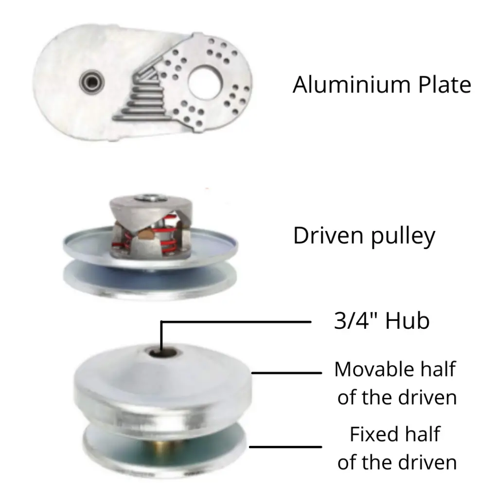
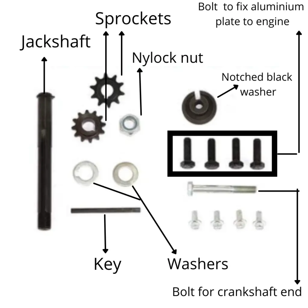
You might have a further disassembled movable half depending on which brand you buy, but assembling that is pretty easy and I will cover that too.
Here’s a labeled diagram with all the parts:
Tools you will require:
15/16 socket or wrench
10 mm socket or wrench
Anti-seize for the bolts
Dremel Grinder or a tin snip cutter
Step by Step process:
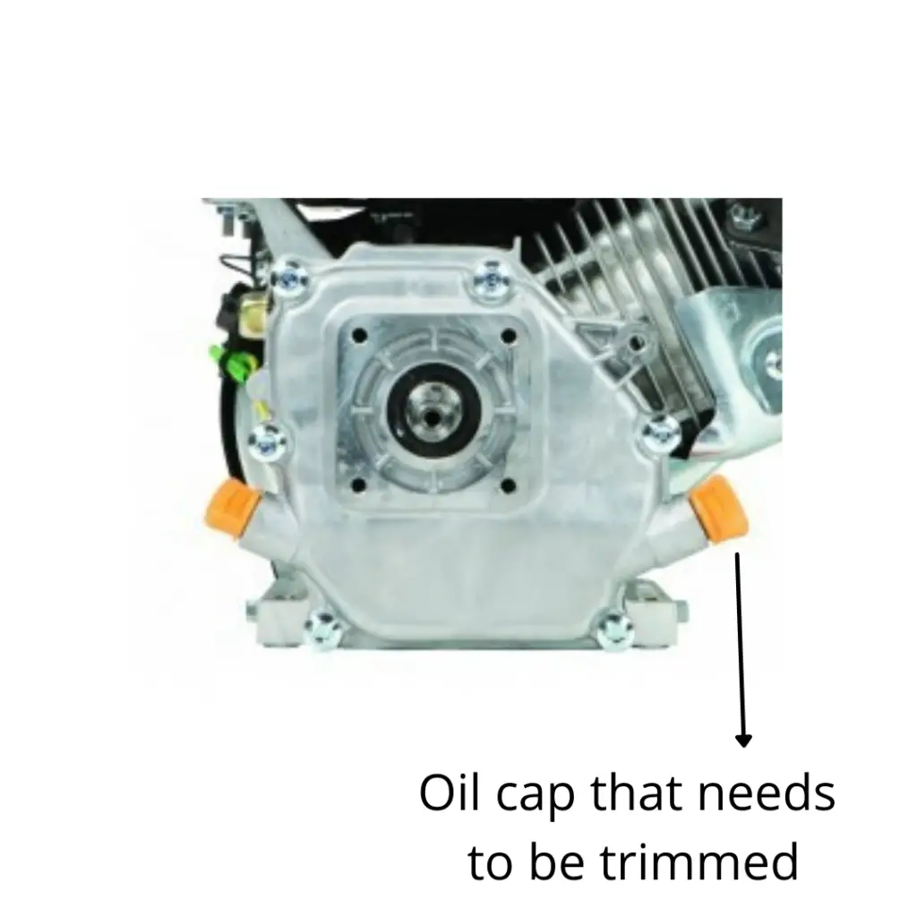
Step 1: Cut the edges out of the plastic oil cap in the engine with a Dremel grinder or a cutter. The edges of the cap hits the backplate of the torque converter and therefore needs to be trimmed off
Step 2: Apply anti-seize into all the bolts, so that they don’t get jammed into the engine and come out easily when you decide to them apart.
Step 3: Align the backplate of the torque converter onto the Engine’s crankshaft, such that the lower middle holes of the backplate align with the holes on the engine.
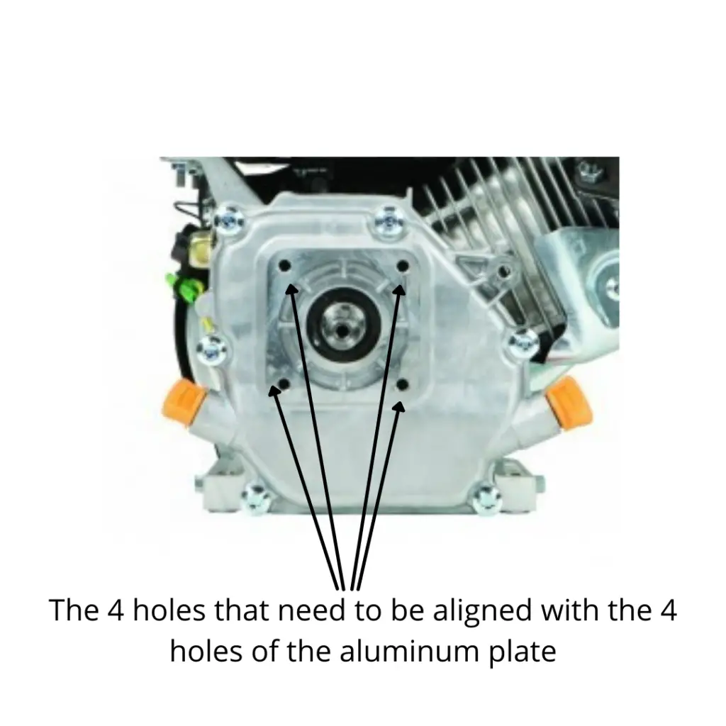
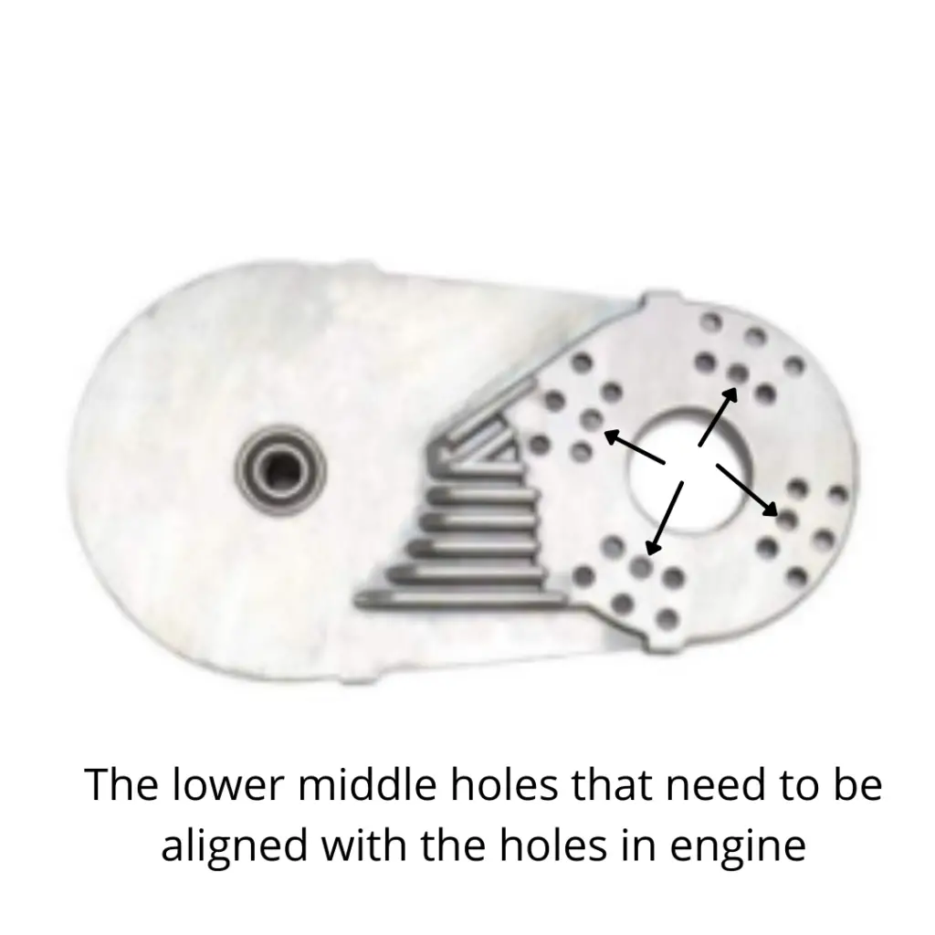
Step 4: Hand tighten the 4 hex cap 5/16 bolts along with their flat washer and lock washer to fix the aluminum plate onto the engine, through the holes. (If you end up losing those bolts, then remember that the bolts are 24 threads, here’s the Amazon link for the bolt)
Step 5: Tighten the 4 bolts with a socket or wrench, only tighten after all the 4 of them are hand tight, if you tighten 1 before hand-tightening the others, they might not align.
Step 6: In the rear end of the aluminum plate, slide in the jackshaft. The jackshaft is not cylindrical, the 2 ends have different diameters, the end with a bigger diameter has a circlip on it. You need to slide the jackshaft in from the smaller diameter end, such that the end with circlip is behind the aluminum plate while the smaller side is on the front side of the plate.
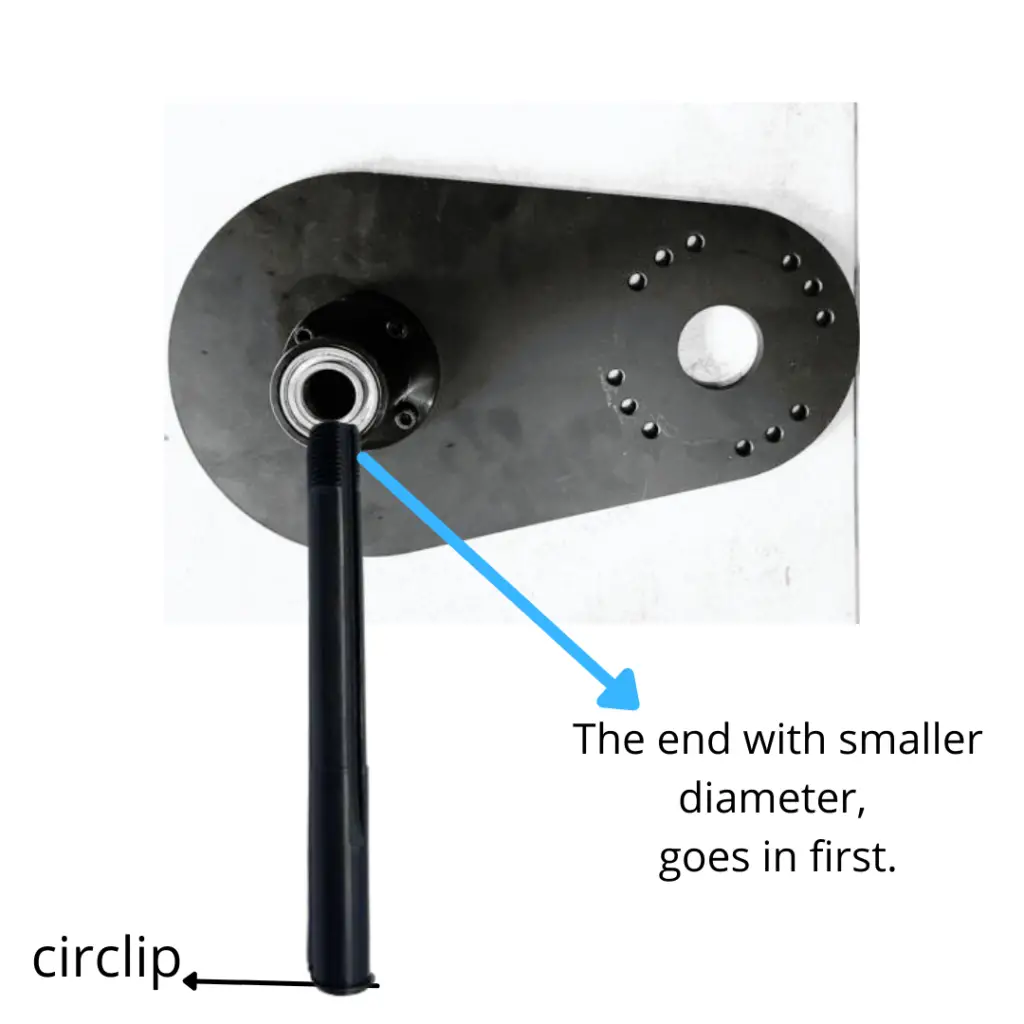
Step 7: Slide the shaft key and the keyed washer onto the jackshaft from the front end.
Step 8: Install the sprocket on the jackshaft by aligning the key and the hole.
Step 9: Install the Driven pulley on the jackshaft.
Step 10: Slide the washer on the jackshaft and then hand tighten the nylock nut.
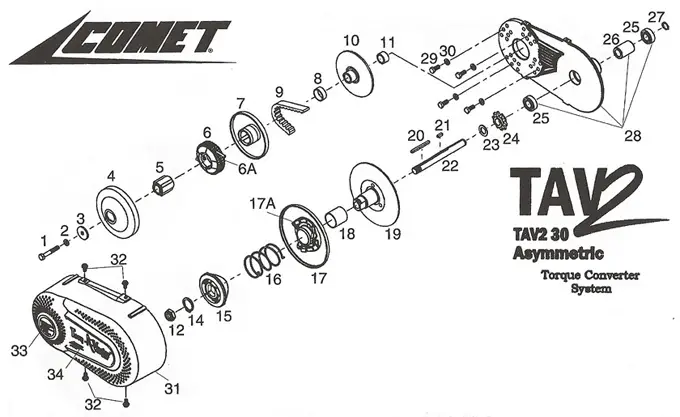
Use this comet 30 series diagram from their manual for reference, part number 15-19 is the driven pulley, 22 is the jackshaft, 24 is a sprocket, 20 is key, 12 is the nylock nut and 14 is the washer, don’t worry about the rest, they all come intact.
Now we move on to install the driver clutch.
Step 11: Slide the 3/4″ washer and spacer onto the crankshaft. These washers and spacers will help you align the 2 pulleys and provide spacing between the fixed part of the driver and the nuts. If the pulleys are not aligned even after installing the spacer and washer, you’ll need to add or remove some 3/4″ washers.
Step 12: Install the fixed part of the driver pulley, such that the cylindrical shaft of the part is facing outwards and the plate is closer to the engine. It is keyed so you’ll need to line that up with the slot in the crankshaft.
Step 13: Slide on the brass bushing.
Step 14: Install the belt between the 2 pulleys, make sure you do this before you slide the driver clutch (movable half). The belt in the 30 series is asymmetric, meaning that one side is more tapered (has an angle) than the other.
The flat side of the belt will be towards the engine, i.e, they will be in contact will the fixed part of the pulley, while the tapered side will be touching the movable parts i.e. the clutch and the movable half of the driven pulley.
Step 15: Slide the 3/4″ hub (part #5 in the above diagram).
Step 16: Slide the movable pulley onto the hub.
Step 17: Put the notched black washer onto the clutch (movable part) of the driver.
Step 18: Fix the driver clutch with the drive Unit Bolt (size: 5/16-24 x 2″) with lock and flat washer.
Step 19: Tighten the bolt in the driver clutch and the nylock nut in the driven with the sprocket or washer.
The max torque recommended in Commet’s user manual is 20 lbs.
If your driver pulley came in more disassembled then use the above diagram, you can easily figure out which part will go in where.
Mistakes to avoid
- Do not assemble your 40 series torque converter using this guide, you will end up wearing out belts at a very fast rate
- Do not Install the hub and driver clutch before you put on the belt, otherwise, you’ll need to stretch the belt and will damage the belt unnecessarily.
- Do not hammer the jackshaft into the drive, Avoid the use of hammer in general.
- Do not install the belt into non Alligned pulleys, Make sure to allign the pulleys with the help of washers and spacers, do not leave it unaligned or your belt will wear out very very quickly.
